Taking you one step ahead
802.1q - supporting VLANs
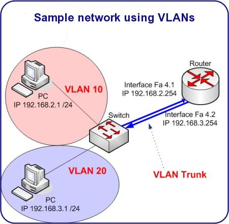
The Raspberry Pi supports Virtual Local Area Networks, also known as VLANs. Not to confuse VLAN with WLAN, which stands for Wireless LAN, the VLAN is having separate logical networks over one physical wiring. It's quite exciting actually, because using VLANs, the Raspberry Pi is capable of being a router-on-a-stick. Let me dig deeper into this by explaining the terms, and the need for VLANs.
The need for VLANs come to light when segmentation plays an important part in one's network. Even in home networks :). However it is easier to imagine a small company network, where different groups of users are separated into different networks. These groups can be viewed as Marketing Team, Accounting Team, Engineering Team and so on. For security reasons, it could be a good idea to create different IP ranges (IP subnets) for each group. These networks can then be joined in a controlled and/or monitored environment. A single entry/exit point can be a good reason for having different networks for each department. But this is all limited to physical proximity. When people start moving into different rooms, floors or even buildings, things get complicated.
VLANs are 4 extra bytes on the layer 2 header, therefore a total of 4096 different vlans can exist in the same physical network. Think of VLANs as tags on network traffic, where switches label or mark every layer 2 frame with a number. This number represents the VLAN itself. After having the frame, the switch makes sure that they can't cross VLAN boundaries without a router, or a network device that is capable of routing packets.
The Raspberry Pi can be such a device. Turning on VLAN support involves two steps. First you need to enable VLAN support on the Raspberry Pi itself. Then, turn on 802.1q on the switch itself where the Pi is connected. You will lose connectivity if you only have a single wired connection, so choose your steps carefully. As you might have guessed already - 802.1q is the standard for VLANs.
To enable 802.1q on the switch, take a look at an example Cisco configuration below:
conf t

interface

switchport mode trunk

switchport encapsulation dot1q

switchport trunk native vlan

end
The above configuration is taken from a simple layer 2 switch, such as the Catalyst 2950 or 2960 series. The encapsulation command can be optional: if the switch supports both ISL and 802.1q trunking, you need to specify the one you're willing to use. Stick with 802.1q, as ISL is a Cisco propietary protocol and is not too common anymore.
On the Pi side, things are a bit more complicated, but nothing to be scared of. Steps are simple. Install userspace tool, load the module and configure the interface. Below are the commands that will make this happen:
root@rpi:~# apt-get install vlan

Reading package lists... Done

Building dependency tree

Reading state information... Done

The following NEW packages will be installed:

  vlan

0 upgraded, 1 newly installed, 0 to remove and 237 not upgraded.

Need to get 40.0 kB of archives.

After this operation, 146 kB of additional disk space will be used.

Get:1 http://mirrordirector.raspbian.org/raspbian/ wheezy/main vlan armhf 1.9-3             [40.0 kB]

Fetched 40.0 kB in 2s (16.7 kB/s)

Selecting previously unselected package vlan.

(Reading database ... 67642 files and directories currently installed.)

Unpacking vlan (from .../archives/vlan_1.9-3_armhf.deb) ...

Processing triggers for man-db ...

Setting up vlan (1.9-3) ...

root@rpi:~#
As you can see, in the above example, we're using Raspbian, one of the available and widespread distros for the Pi. The initial interface config looks like this:
root@rpi:~# ifconfig

eth0      Link encap:Ethernet  HWaddr b8:27:eb:19:9d:ca

          inet addr:10.0.0.5  Bcast:10.0.0.127  Mask:255.255.255.128

          inet6 addr: 2001:470:1f0b:19e7:ba27:ebff:fe19:9dca/64 Scope:Global

          inet6 addr: fe80::ba27:ebff:fe19:9dca/64 Scope:Link

          UP BROADCAST RUNNING MULTICAST  MTU:1500  Metric:1

          RX packets:440 errors:0 dropped:0 overruns:0 frame:0

          TX packets:299 errors:0 dropped:0 overruns:0 carrier:0

          collisions:0 txqueuelen:1000

          RX bytes:36179 (35.3 KiB)  TX bytes:34494 (33.6 KiB)
As you can see, the eth0 address is 10.0.0.5, this is a pre-vlan configuration. Let's load the module that is responsible for vlans, and start adding vlan interfaces to the physical:
root@rpi:~# modprobe 8021q

root@rpi:~# vconfig add eth0 2

Added VLAN with VID == 2 to IF -:eth0:-

root@rpi:~# ifconfig -a

[..]

eth0.2    Link encap:Ethernet  HWaddr b8:27:eb:19:9d:ca

          inet6 addr: fe80::ba27:ebff:fe19:9dca/64 Scope:Link

          UP BROADCAST RUNNING MULTICAST  MTU:1500  Metric:1

          RX packets:0 errors:0 dropped:0 overruns:0 frame:0

          TX packets:5 errors:0 dropped:0 overruns:0 carrier:0

          collisions:0 txqueuelen:0

          RX bytes:0 (0.0 B)  TX bytes:398 (398.0 B)
As you can see, we have added vlan number 2 to interface eth0, and a new interface just came to life: eth0.2. .2 represents what we call a subinterface and can accept tagged (labelled) traffic. IP address can be assigned to this logical interface, and in general, this can be treated just like any other interface on a linux. Can be used for NAT, firewalling and everything else.
root@rpi:~# ifconfig eth0.2 10.0.0.4 netmask 255.255.255.128 broadcast 10.0.0.127 up

root@rpi:~# ifconfig eth0.2

eth0.2    Link encap:Ethernet  HWaddr b8:27:eb:19:9d:ca

          inet addr:10.0.0.4  Bcast:10.0.0.127  Mask:255.255.255.128

          inet6 addr: fe80::ba27:ebff:fe19:9dca/64 Scope:Link

          UP BROADCAST RUNNING MULTICAST  MTU:1500  Metric:1

          RX packets:0 errors:0 dropped:0 overruns:0 frame:0

          TX packets:6 errors:0 dropped:0 overruns:0 carrier:0

          collisions:0 txqueuelen:0

          RX bytes:0 (0.0 B)  TX bytes:468 (468.0 B)
root@rpi:~#
And pinging the gateway on this new network, is a success:
root@rpi:~# ping 10.0.0.1

PING 10.0.0.1 (10.0.0.1) 56(84) bytes of data.

64 bytes from 10.0.0.1: icmp_req=2 ttl=255 time=0.823 ms

64 bytes from 10.0.0.1: icmp_req=3 ttl=255 time=0.720 ms

64 bytes from 10.0.0.1: icmp_req=4 ttl=255 time=0.873 ms
Happy VLANing!
- Log in to post comments